A long time ago (in IT years), I started my professional career as a network engineer. I spent the next ~10 years troubleshooting, designing, and implementing networks for lots and lots of companies before I began to transition into DevOps and then software engineering.
I was really drawn to networking early on because it just “clicked” with me, for one reason or another. One of the things that helped me early on is that network protocol definitions (RFCs, usually) have a long history of including diagrams of protocol data structures. It helped me to see which bits or bytes of a header were where and how they related to each other. And, when something wasn’t working quite right, I could fire up Wireshark (Ethereal at that time) and visualize how the machines were talking (or not talking, depending on the situation). Seeing the same packet structures from real data that I saw in RFCs and textbooks felt like the best - and the nerdiest - type of magic.
Although this has a long tradition in networking, other systems also require structure, and visualizing that structure can be just as powerful when learning about them. Which brings me to this post, Anatomy of a Filesystem: xv6. The idea behind “anatomy” here is to focus on the structure of a filesystem. What is its overall structure? What are the critical sub-structures? How are these structures represented? In this post, we’ll look at the filesystem of a small operating system to see what some of the critical structures actually look like.
To support this article, I’ve also created a small CLI utility for inspecting real xv6 filesystem
images. I call it xv6fs, and you can find it on GitHub. In addition, in that repo,
you’ll be able to find a sample image file so that you can follow along if you’d like!
Note: Please look for the v0.1.0 release for xv6fs binaries and the sample image (fs.img). I have tried to build for common combinations of OS and CPU architecture. If you can’t find one for your system, you may need to build from source using Zig 0.15.2. The sample image should work for any OS you’re running, though.
Brief Overview of Filesystems Link to heading
A filesystem is one of the core concepts in an operating system. It is the interface between what you and I call “files” or “directories” and specific blocks of bytes on a disk. There are many different filesystems supported by most modern operating systems, offering different performance and availability characteristics. But, ultimately, they exist to keep track of where data is persisted and to provide users with access to that data when they need it.
Why xv6? Link to heading
I’ve decided to focus on the filesystem that is built into the xv6 operating system. xv6 is a teaching operating system developed at MIT and used by many people to learn OS concepts. It is based on early UNIX systems, and it contains the core features of an OS, but without the complexity of modern systems.
Like its other components, the xv6 filesystem is cut down to the most important essentials that aspiring systems programmers should know. The filesystems you’ll find in the “real world” have benefitted from decades of learning and optimizations for real workloads. This adds complexity, which is critical for actual usage, but not so critical for seeing the most important bits of a filesystem.
The typical workflow for students is to hack on the OS internals and then boot it up in
QEMU, using make qemu. As part of the Makefile, the build will construct a filesystem
image, named fs.img, if one is not already present. This file contains the contents of what we’ll
look more closely at throughout the rest of the post.
Note: Throughout this post, when I show
xv6fscommands that refer to filesystem image files, I will call them “fs.img” for simplicity. You’ll need to provide the path to your image files, though.
The 50,000 Foot View Link to heading
Let’s start by getting a big-picture look at what’s actually in an xv6 filesystem. If we run
./xv6fs info fs.img, we’ll see something like this:
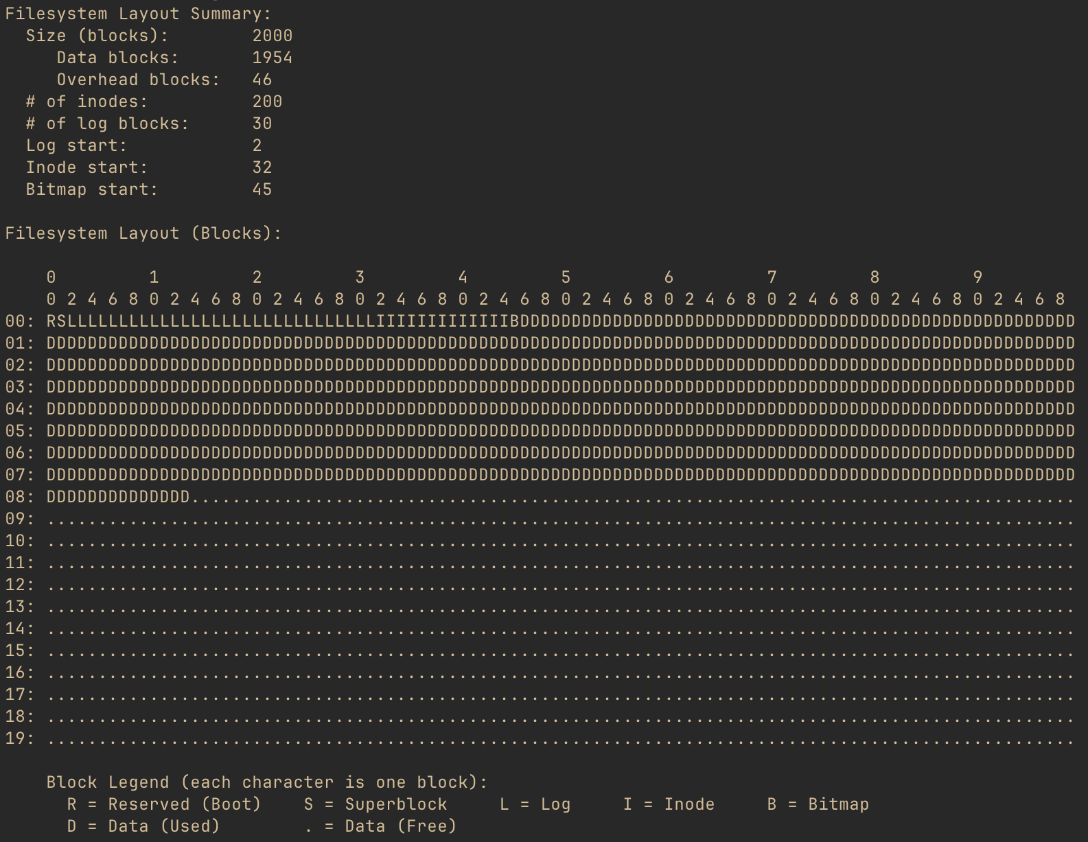
The pseudo diagram shows what each block of the filesystem is used for. But, what is a block? A block is the smallest chunk of storage space that the filesystem will allocate for any purpose.
The xv6 filesystem’s block size is 1024 bytes. So, every character shown in the diagram indicates the purpose of that particular chunk of 1024 bytes. And, the layout summary for this filesystem image shows that there are 2000 such blocks. Of those 2000 blocks, 46 are used by the filesystem in order for it to operate, and we’ll be going into detail on those blocks. All of the “D” and “.” blocks are either in use by files in the filesystem or available to be allocated to such files, respectively.
Superblock: The Table of Contents Link to heading
At block number 1 (not to be confused with block number 0) is the superblock. The superblock contains enough information for xv6 to find any of the key data structures of the filesystem.
In the xv6 source code (file kernel/fs.h) the superblock is defined as below:
struct superblock {
  uint magic;        // Must be FSMAGIC
  uint size;         // Size of file system image (blocks)
  uint nblocks;      // Number of data blocks
  uint ninodes;      // Number of inodes.
  uint nlog;         // Number of log blocks
  uint logstart;     // Block number of first log block
  uint inodestart;   // Block number of first inode block
  uint bmapstart;    // Block number of first free map block
};

#define FSMAGIC 0x10203040
This is really all that’s needed for the OS to validate the filesystem and to locate every
important filesystem structure. We will talk about most of these fields, but one that is worth
mentioning here is magic, or the “magic number.” It’s common for binary files to include such
a magic number, a static value that helps programs reading the file to identify its type. They
are chosen arbitrarily, and xv6 has chosen the 32-bit number 0x10203040. If the first 32 bits
of the superblock don’t match this value, the filesystem is invalid, and the OS should proceed no
further.
A uint is a 32-bit (4 byte) unsigned integer. There is no padding between the fields of the
superblock, so since there are 8 32-bit fields, the superblock uses 32 bytes of its 1024 byte
block. So, taking the values from what we saw in xv6fs info above, this is what we’d imagine
the superblock to look like (well, minus the unused 992 bytes):

Let’s check our hypothesis! If we run ./xv6fs dump fs.img -b 1, we can see a hex dump of block
number 1: the superblock.
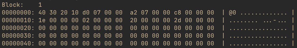
Huh, well that’s disappointing. Right at the beginning, we expect to see the magic number,
0x10203040, but what we see is 0x40302010. Notice that all of the other 4-byte chunks are
also backwards. So, what gives?
As it turns out, xv6 uses little-endian layout for its filesystem structures. This means that the least significant byte of any multi-byte values will be stored, physically, ahead of more significant bytes. Do note that this only applies to multi-byte values. A single byte is always a single byte. But when a type needs more than one byte for representation, xv6 will put the LSB (least significant byte) first and the MSB (most significant byte) last.
We’re going to talk about the key filesystem data structures in later sections and relate them back to how the superblock allows for finding them. But, first, let’s take a quick detour to answer the question, why isn’t the superblock actually the first block if it’s so important?
Boot Block: What’s Before the Superblock? Link to heading
Before an operating system can load a filesystem, there has to be a running OS. The code that does the initial bootup has to be stored someplace, and it needs to be somewhere that the processor can easily find in order to load the boot instructions up.
One common technique, particularly early on, was for the first block to include these boot instructions. xv6 reserves the very first block for this, to follow convention, however it does not actually use it for anything. It relies on other means, such as QEMU configuration, for the (virtual) processor to load the kernel. This is why block 0 is empty, and the superblock is at block number 1.
Inodes: From Names to Bytes Link to heading
Next, let’s take a look at an incredibly important structure type in the xv6 filesystem: the inode. From the operating system’s perspective, the inode represents a file, a directory, or even a device on the filesystem. Every inode has a unique number, and through directory structures, the filesystem allows the OS and users to locate any object by name. We’re going to look at this in more detail, but first, let’s take a look at how inodes are defined.
Back in kernel/fs.h, there is a structure, dinode which describes the on-disk
format of an inode:
struct dinode {
  short type;           // File type
  short major;          // Major device number (T_DEVICE only)
  short minor;          // Minor device number (T_DEVICE only)
  short nlink;          // Number of links to inode in file system
  uint size;            // Size of file (bytes)
  uint addrs[NDIRECT+1];   // Data block addresses
};

// This is not right here in the source, but for blog context:
#define NDIRECT 12
We saw earlier that the superblock has a record of the number of inodes in the filesystem. In the
xv6fs info output, we also saw a number of “inode blocks.” These blocks contain all of the
inodes for the filesystem - essentially, a lot of the structs described above, in a row.
Aside: There is also a separate structure for the in-memory representation of an inode. It contains additional runtime information that allows the OS to operate on open files. But that’s a physiology lesson, and we’re talking about anatomy here. Curious readers should look for
struct inodein kernel/file.h.
There are a few types of inodes, defined like so in kernel/stat.h:
#define T_DIR     1   // Directory
#define T_FILE    2   // File
#define T_DEVICE  3   // Device
If an inode has a type field that equals 1 (T_DIR), it is a directory, 2 (T_FILE)
is a regular file, and 3 (T_DEVICE) is a device.
The nlink field indicates how many names within the filesystem structure refer to this inode.
Commonly, an inode will have a single name. However, there are also often cases where you may
want to have a second name within the filesystem refer to the same inode - this is known as
linking. (Specifically, in OS terminology, this would be known as a “hard link” as opposed to a
“symlink.”) When there are no longer any links to an inode, that inode is effectively deleted
because there is no longer any way for a user to access the inode.
The inode also includes the size of the file. We discussed earlier that the filesystem allocates
space by 1024-byte blocks. However, most files won’t be an even multiple of 1024. The size
captures how much space is actually used. It tells users or processes reading the file
how many bytes of actual data exist.
For directories and files, the inode needs to maintain a reference to each data block allocated
to the inode. This is where the addrs array comes into play. This is a 13-element array of
uint, where each element is a block number. The first element in the array contains the block
number of the first data block, the second element maps to the second data block number,
and so on until the twelfth element. These are the “direct blocks.” Because each block is 1024
bytes, this means that the first 12,288 (12KiB) bytes of a file may be found by looking up the
inode and then cycling through the blocks identified in the first 12 spots. The final addr
element is kind of special - we’ll talk about it more in a bit.
As the comments for major and minor indicate, these fields are only relevant when the inode is
a device. There is an idea in UNIX that says “everything is a file.” This applies just as
much to I/O devices as it does to what we think of as files. Devices in xv6 can be named and
therefore found in the filesystem’s tree, but instead of mapping to disk blocks, these inodes
tell the OS which device it actually refers to.
Files Link to heading
That’s a lot of text, but I promised pictures! Let’s take a closer look at a file inode. Running
./xv6fs stat fs.img -i 2, we can see the details of the second inode, which you’ll have to take
my word for right now, is a file.
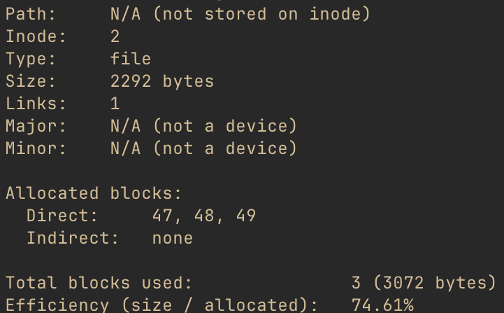
One thing to pay attention to is the “path,” which is the name of the file. A file name is not part of the inode - the name is a link (described above) to the inode. We’ll see how those names get mapped to inodes shortly. The inode does, however, “know” that there is a single link to it.
Given the struct dinode definition above, along with this output, let’s take a guess at what
this would look like. (Remember that all xv6 filesystem structures are little-endian, including
inodes.)

This is the second inode on the filesystem, so where is it? Well, remember that the superblock
told us the first inode block was number 32. Each inode is 64 bytes. So, if we looked at offset
128 (hex offset 0x80) of block 32, we should find the inode we’re interested in. Running
./xv6fs dump fs.img -b 32 and then honing in on that offset reveals the following for inode 2.
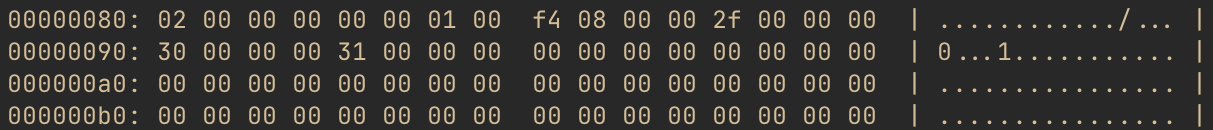
Nice!
Let’s take a quick peek at what’s actually in this file. We have all of the data block numbers,
so let’s look at the first few lines of the first one. Running ./xv6fs dump fs.img -b 47, we
get something like this:
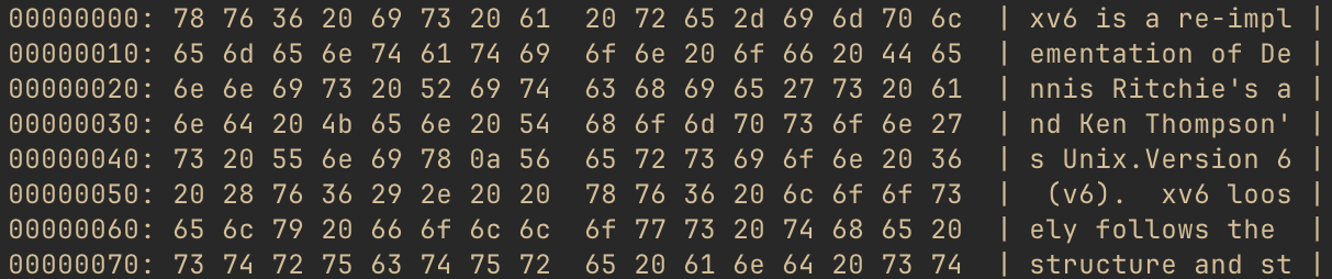
As you may surmise from the right-hand side of the output, this file is actually the README for
xv6, which is included in the filesystem when building using make qemu. It’s convenient to have
a text file to cat in the OS, so why not the project README? Regardless, at this point, we’re
seeing what you may think of as “actual” data, not filesystem overhead.
Note: If you’re following along using xv6fs, you can also use the
-ior--inodeflag with thedumpcommand to dump all the data blocks associated with an inode. This way, you don’t have to run the tool over and over to get each one. And, if you only want to see the file’s full contents, not the hex dump of each block, you can use./xv6fs cat fs.img -i <inode number>instead.
We’ve seen that inodes don’t have names. But we know that, of course, we can reference files by name. So, let’s take a look at how this mapping works next.
Directories Link to heading
Directories are inodes, just like files are inodes. However, the contents of the data block(s) of directory inodes are not “user data,” but rather sets of another xv6 filesystem data structure type: the directory entry (“dirent”).
Once again back in kernel/fs.h, we find struct dirent:
struct dirent {
  ushort inum;
  char name[DIRSIZ];
};

// This is not right here in the source, but for blog context:
#define DIRSIZ 14
As the field names suggest, a dirent contains an inode number (inum) along with a name. When a user wants to access a file by name, the OS will search the directory entries until it finds a matching name and then return the pointed-to inode. (If no matching name is found, the user would get a “file not found” error.)
The name follows C string conventions, in that names are 0 terminated. However, for
simplicity, xv6 elects to cap the name of each entry at 14 characters. Because the inum is a
two-byte ushort, this also conveniently fixes the dirent size at a nice, round, length of 16
bytes, which also happens to evenly divide into 1024. This means each data block of a directory can
hold 64 dirents.
We know, from above, that inode 2 is the project README. Assuming it has a dirent name of “README,” we’d expect its dirent to look like this:

Remember this: we’re going to come back to it shortly and see if we were right. First, we need to know how to find the directory where this dirent would even be!
UNIX-based filesystems are based on tree data structures, with a single root, branches and leaves extending from there. You can find any file in the entire filesystem by traversing the correct path through the tree. Leaf inodes are files or devices; branch inodes are other directories.
If you’re familiar with MacOS or Linux, for instance, you’ve probably noticed that absolute paths
all start with a /. The / is the filesystem root directory, and, as you may have guessed, it’s
just another inode!
The only really unique thing about this inode is that the OS has to “know” where to find it. Just
like xv6 requires the superblock to be at block number 1, the root is always inode number 1. (Tip
for curious readers: If you want to look for this in the xv6 source, look for ROOTINO.) Let’s
take a look at that inode.
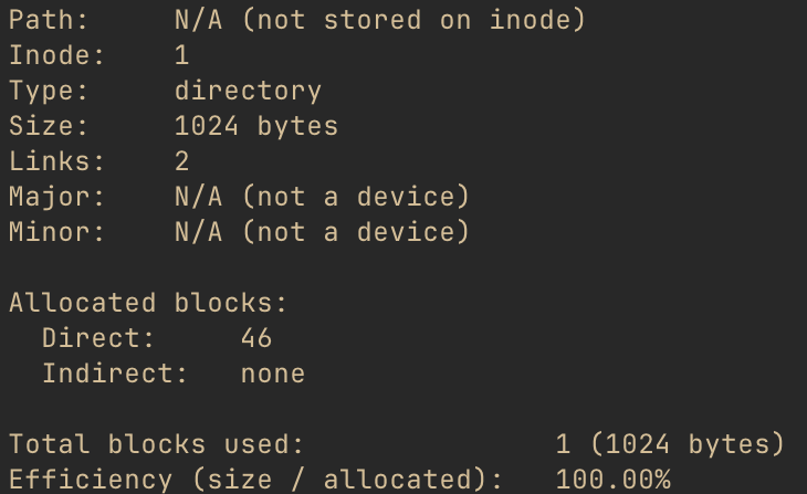
Note that there is still no path stored on this inode, just like any other inode. xv6 just has a static mapping from “/” to the root inode number, which it uses to resolve paths to inodes.
Let’s get a sense of what’s inside the root directory, using ./xv6fs ls fs.img -i 1 (you could
also use the path, ./xv6fs ls fs.img / instead).
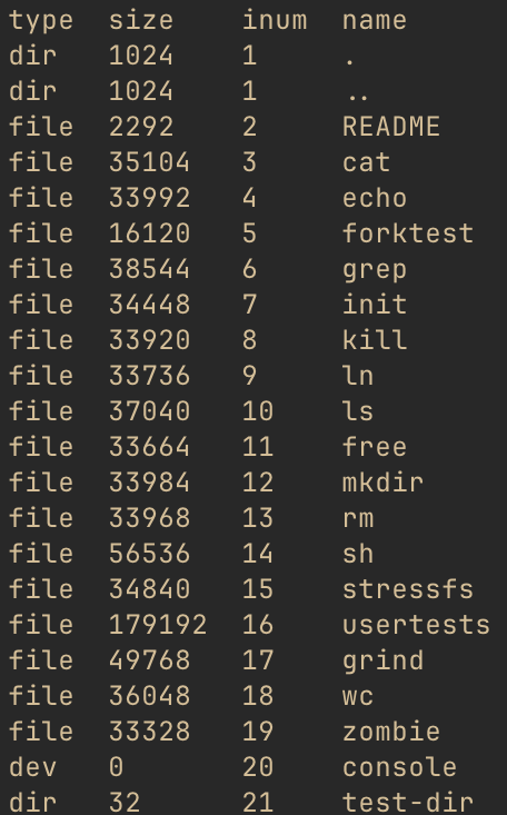
Cool, so this confirms that the “name” of the README is, in fact, “README.” It also looks to be
the third directory entry (we’ll come back to those first two). We also know from the stat above
that the root inode has one data block, block number 46. Since each dirent is 16 bytes, and the
README is the third dirent, we should find it at offset 32 (hex 0x20) inside that data block.
Let’s see if we were right up above, by doing ./xv6fs dump fs.img -b 46 and focusing on that
offset:

Neat! Looks like we were right!
Going back to the previous xv6fs output, notice that we also see the inode types of each entry
in the directory. It did a little extra work to determine the type and size (it iterated
through the dirents, fetching each inode to get the type and size). But note that dirent inodes
don’t have to be file inodes. A directory entry can refer to other directories, which could
also refer to even other directories, to produce a filesystem tree structure. Additionally, note
that the console inode is a device.
The directory test-dir is one that I put in there to show another directory because the
default “fs.img” does not include subdirectories. Let’s look at its directory listing, with
./xv6fs ls fs.img /test-dir
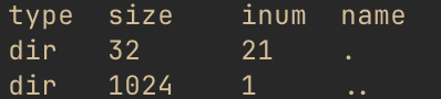
OK, admittedly not the most exciting thing in the world, but it is kind of interesting to see the same “.” and “..” entries we noticed in “/” as well. When creating directories in xv6, it will automatically create these two entries, to simplify relative path traversal. “.” refers to “this directory” - you’ll notice it has the same inum as “test-dir” did in the listing above. “..” refers to the parent directory, which you’ll notice is the root inode number.
At runtime, these simplify the work for users wishing to use relative paths instead of absolute paths. To be fair, there is also additional runtime information needed to make this happen, as each process also keeps track of its current working directory inode, so it has ready access to these relative paths. But, this is the purpose of these two odd-looking entries.
Why is the inum for “..” still 1 in the root inode? Well, there is no “up” from the root inode: it’s the root of the tree, after all. So, for the case of the root directory, both “.” and “..” point to itself.
We’ve now got a good handle on what inodes are and how they allow the filesystem to map from names to actual data. We also know that there are 13 data block references in each inode, and each block can be 1024 bytes. But, that’s not that much space, really. Let’s take a quick peek at how xv6 enables larger files.
Indirect Blocks: When NDIRECT Isn’t Enough Link to heading
In the intro to inodes, we mentioned that the first 12 address entries point to the inode’s data blocks. Since each block is 1024 bytes, this means that these blocks could store, at most, a total of 12,288 bytes (12KiB). But, there aren’t 12 address blocks - there is a 13th one too! When more than 12KiB are required, xv6 will allocate an indirect pointer block and put its address into the 13th spot.
The format of this indirect pointer block is actually pretty straightforward. Block numbers are unsigned 32-bit (4-byte) integers, and this block just contains a sequence of these 4-byte addresses. Each of those pointed-to blocks contains (up to) another 1024 bytes of the file’s contents.
Let’s look at it more closely. One large file in the filesystem image is called usertests. We
can stat it to get a look at this inode (note that xv6fs also allows statting by filename, but
we’ve used inodes until now pedagogically). ./xv6fs stat fs.img usertests gives us output
that starts out:
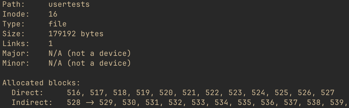
This file is 179,192 bytes, definitely larger than 12,288, so it requires indirect blocks. The
stat output shows the block ID of the indirect pointer is 528. It points to 529, 530, 531, etc.
We would expect, then, that the contents of block 528 would start out looking like this…

… and, indeed, that is what we find when we do ./xv6fs dump fs.img -b 528:

The indirect pointer design has some important implications. xv6 has only one indirect pointer block per inode, so the maximum file size is limited by how many blocks it can point to. With 4-byte block addresses and 1024-byte blocks, it can point to 256 other blocks, max. That yields a maximum file size of 12KiB (direct) + 256KiB (indirect) = 268KiB, or 274,432 bytes.
Other filesystems have other scaling mechanisms. This is another example of xv6 choosing simplicity over complexity for teaching purposes - scaling mechanisms don’t really teach too much more about filesystem fundamentals, so there is no need to include them. But, you could imagine there are other techniques to provide larger file sizes.
Another, more subtle, implication relates to performance. When reading data from one of the direct
blocks, the OS has to look up the block ID from the inode and then read that block. For indirect
blocks, the OS has to look up the indirect pointer ID, and then look up the appropriate
indirect block before finally reading the data. Disk operations are extremely slow by software
standards, so following on-disk pointers is not ideal. Real operating systems make extensive use
of caching in order to improve performance. Indeed, even xv6, which we’ve seen generally
make simplifying design choices, includes caching for disk operations. This is a runtime
(physiology) matter, but interested readers should look for struct buf in the xv6 source.
Inodes are critical to the design of UNIX-based filesystems, and they directly relate to “actual”
user data. There are a couple of other important xv6 filesystem “bookkeeping” structures that we
saw referenced earlier in the xv6fs info output. We’ll look at those next.
Bookkeeping Link to heading
Free Space Map: Finding Data a Home Link to heading
A filesystem is not static - files and directories may be added, deleted, and edited. When a new file is added, the filesystem needs to allocate an inode, of course, but it also needs to find someplace for that inode’s data to go. The same is true when a file grows beyond a single 1024-byte data block, as the filesystem needs to find another block. And, if a file is deleted, and there are no more links to an inode, its data blocks should be freed so that other inodes could use the space if needed.
In short, the filesystem needs to keep track of which blocks are free and which are not. That brings us to the free space bitmap.
The bitmap is actually a fairly simple structure, which efficiently tracks block usage. All the filesystem needs to know about a block is, “is it used, or is it not used?” That’s a binary question, and its answer can be represented as a 1 or a 0. If we had one giant “blob” of bits, where the index of each bit corresponded to a block ID, we could just check whether that position was a 0 or a 1 to know whether the block had been allocated. And, this is just what the free space bitmap is!
Conceptually, it looks like the following, although we’ll see it’s subtly not quite how xv6 does it:

A single block storing a free space bitmap could, therefore, handle a filesystem with up to 8192 blocks (1024 byte block * 8 bits per byte). For the filesystem image we’ve looked at, one bitmap block is, therefore, more than enough. You may have noticed the superblock did not track how many bitmap blocks there were, only where they started; it can easily calculate how many bitmap blocks there are by using this math and comparing to the size of the filesystem.
The block numbers shown here are not arbitrary; if you look back at the output of xv6fs info
from earlier in the post, you’ll notice that it shows that block 814 is the first free block. So,
this is logically what we’d expect of the bitmap in our example filesystem image.
Just like xv6 uses little-endian ordering for multi-byte data types, it does something similar for its free space bitmap. Where the diagram above shows offset 0 representing block 0, xv6 instead groups blocks by 8 and stores the least-significant block ID in the 8th position and works back to the most significant bit.
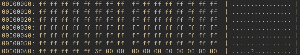
With that in mind, let’s zoom in on the byte of the bitmap that contains our transition from the last few allocated blocks to the first free ones. Specifically, let’s look at byte 101 of the bitmap, which will include bits for blocks 808-815. Here’s what this would look like, again recalling that 815 will be the first bit and 808 will be the last.

This works out to hex value 0x3f, so that’s what we’ll expect to see in byte 101 in the free
space bitmap. The xv6fs dump command groups output into 16-byte lines, so we’re going to
run xv6fs dump fs.img -b 45 and hone in on the line at offset 96 (0x60).

There we go!
Using this bitmap, whenever the OS needs to allocate a new data block, it can skim the bitmap and look for a 0 bit. The corresponding block is free. It can then set it to 1 and assign the block number to an inode. Likewise, in the case of a file being deleted, the OS can set each corresponding bit position to 0, signaling that they are free to allocate to other inodes in the future.
Logging: Protecting Data Even When Things Go Wrong Link to heading
And, with that, we’ve looked at most of the major structures found within the xv6 filesystem! The remaining type is a redo log, though its structure is minimal. Filesystem logging is much more “physiology” than “anatomy,” but there is still some interesting structure we can evaluate. Before we do, though, we do need to take a brief physiology detour, consider the problems that logs solve, and get a sense of how they behave.
Writing to Disk: What Could Possibly Go Wrong? Link to heading
Computers have a nasty tendency to crash on occasion. This can be due to software faults, hardware faults, or loss of power. Unfortunately, we don’t get much choice in when this happens, either. (Based on personal experience, it tends to be the worst possible time.)
Considering the filesystem structures we’ve discussed, let’s think about what might happen if we created a new directory, as an example. What filesystem structures change? Well, we know that a new inode will be created, so at least one of the inode blocks will need to be updated. The directory inode containing the new directory will need a dirent for it, so one of its data blocks also needs updated. We also need to find a location to put the new directory’s data, so the free space bitmap needs updated as well. And, of course, the contents of the new directory will be written to whichever data block(s) the OS found for it in the bitmap.

This is a lot of writing to disk. Failure to make the appropriate updates to every block described would lead to an inconsistent state. Hypothetically, consider what it would mean if the computer crashed during this process, and the bitmap were the only block not updated before the crash. Well, the next time the OS started up, it would think that a block was free, but which had already been allocated to an inode. It would then give that block out to the next requested inode, and suddenly, two inodes are clobbering each other’s data. Take a few minutes to think about what happens if any of the other blocks don’t get written as well. (Hint: It’s never good.)
This brings us to the idea of a transaction. In computing, a transaction refers to a set of operations that must either all occur, or none must occur. Techniques for handling transactions are varied and are critical in both operating systems and distributed systems. One way to handle transactions is to, first, store a description of all the changes before telling the source that the change they requested is complete - this is the technique xv6 uses.
The idea is: When a disk write occurs, calculate the new block data for every block involved. Write each of these blocks to special-purpose overhead blocks, essentially a scratchpad, not to their actual locations. Then, update an on-disk structure to signal that all of the appropriate scratch blocks are written. Begin updating the actual blocks by copying the contents from the scratch blocks into them. Once all have been copied, update the on-disk structure to signal the write is complete.

The key insight is that none of the final blocks are touched until all of the data in all of the changed blocks is stored somewhere. The transaction is not crash consistent (recoverable) until the OS writes the count of data blocks to a specific location (the first log block). However, once that happens, the data in that transaction may be recovered, even following a crash.
At this point, the OS writes the data from the scratch blocks over the previous data in the relevant non-log blocks. If this completes successfully, the count is reset in the log header.
However, imagine that the power failed during step 4 in the diagram above. The machine would come back online, and while the OS started up, it would find a non-zero count in the log header. It could then simply begin copying from the “scratch” blocks to the actual locations, eventually clearing the count once it finished. Re-writing over blocks that had already changed makes no difference. Because only one transaction is tracked at a time, these changes are fully idempotent, so the changes can be replayed over and over again, as needed, until the transaction finally completes.
Structure of a Log Link to heading
Not to put too fine a point on it, but it’s important to note: the data in the scratch blocks will be identical to what will eventually go into the final location. This means, if a block is being used to temporarily store an inode block, there will be inodes in it. If it’s a data block, it will be whatever data belongs to the file or directory. If it’s a bitmap block, there will be a bitmap. The structure in these blocks is exactly the same type of structure we’ve seen already.
The very first log block holds the log header, though. It’s quite minimal, really. In kernel/log.c, we see the log header definition:
struct logheader {
  int n;
  int block[LOGBLOCKS];
};

// This is not right here in the source and is actually
// calculated in regards to a different #define, but for
// blog context:
#define LOGBLOCKS 30
The header for the current transaction is written to the first log block when updated copies
of all of the relevant log blocks have been written to other log blocks. The block array stores
a list of the block numbers associated with the following log blocks. The field, n, indicates
how many of the following log blocks are part of this transaction.
Inspecting this with xv6fs is certainly possible, although catching a filesystem in the midst of
a transaction is unlikely, at least without adjusting the kernel to trigger some bad behavior.
But the OS has no need to clear the other log data. Once the log header’s count is zeroed, any
leftover data in the scratch blocks is simply ignored, which means there should be remnants of
previous writes even after the transaction completes. Let’s go spelunking and see what we can see.
Note: If you’re following along with xv6fs and using my sample image, this is what you should see. However, the contents in the log blocks are far more likely to diverge from mine if you are using an image of your own. The rest of this discussion should still help you decipher what’s in your image, though.
Let’s start by dumping the first log block: ./xv6fs dump fs.img -b 2.

OK, so we know from the struct logheader definition that the count (n) will be the first four
bytes of the header. As expected, it is zero - this filesystem image must not have any transactions
in flight. But, we do see some non-zero values following it. I’ll save you the little-endian and
hex-to-decimal conversions and tell you the numbers listed are: 33, 45, 813, 46, and 32. Those
look a lot like some of the block numbers we’ve already seen in previous sections.
Picking one, we know that block 45 is the free space bitmap block in this filesystem image. So,
what happens if we dump the contents of the log scratch block corresponding to block 45? We can
do that! This is the second item in the list, which means it will be in the second “scratch” block.
Because the log header consumes the “zeroeth” log block, we can actually just index from the
start of the log blocks to get it. That would put it at 2 (log block start) + 2 (position in the
scratch block list) = block 4. Let’s do ./xv6fs dump fs.img -b 4.
That looks an awful lot like a free space bitmap to me!
If you’re curious, the changed blocks are from the last change I made to this image, when
I created the /test-dir directory that we looked at previously. (Also, why I chose that example
for the log diagrams earlier!) test-dir’s inum, 21, puts it on the second inode block because each
inode block can hold 16 inodes. That means, block 33. It of course needed to find a free block
in the bitmap (block 45), and the first block found was 813, which would have had “.” and “..”
dirents added to it by the OS. The dirent for the root is in block 46, as we saw, and since we
added a link to /test-dir, block 46 needed a new dirent added to it as well. And, because
/test-dir’s dirent for “..” points back to the root, the root inode (stored on block 32) needed
its number of links incremented. So, for this small change, we touched five different blocks!
Conclusion Link to heading
And with that, our look at the anatomy of the xv6 filesystem has come to an end. This is a simpler filesystem than those you’d find in modern operating systems, but as we’ve seen, there is still a lot of nuance to be found just looking at the most essential parts of a filesystem.
I’ve learned a lot from studying the xv6 filesystem and preparing both xv6fs and this blog post. I hope that if you find yourself studying filesystems or xv6 that the diagrams and “live” examples in this post can help you!